The following application story is taken from the “THE VALUE OF FIELD MEASUREMENTS ON OVERLAND CONVEYORS” by David J. Kruse and Ryan Lemmon of Advanced Conveyor Technologies (AC-Tek). The TorqueTrak 10K temporary torque measurement system was used to provide the torque data.
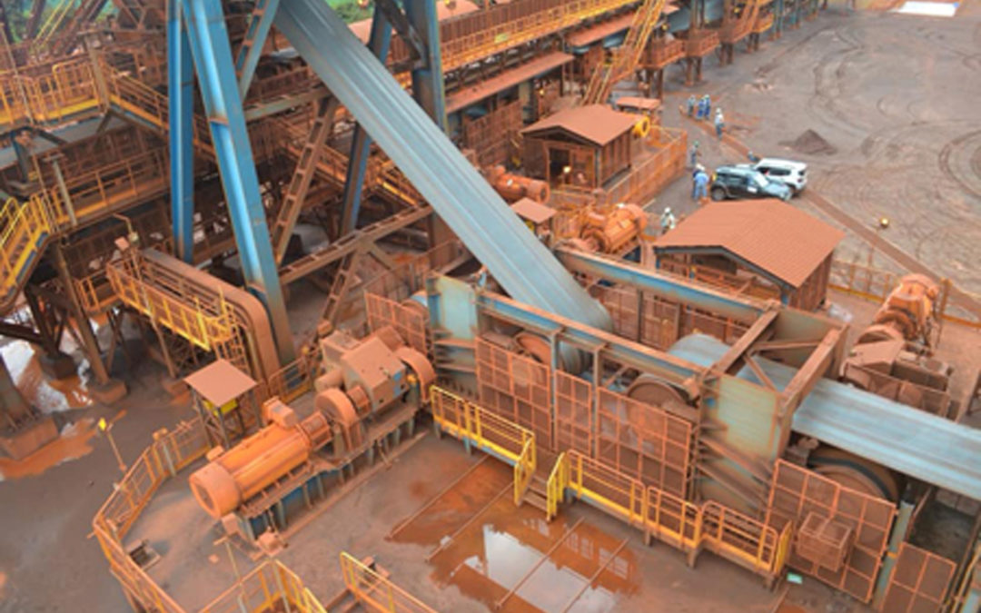
“The first conveyor installation is located inside the Arctic Circle with extreme temperatures variations from -40°C to +25°C. This particular conveyor was one of several new systems. It is over 3 km in length with approximately 200 m of elevation gain and transports 8000 t/h of copper ore. The conveyor has four VFD drives totalling 9200 kW of installed motor power.
During commissioning there were significant vibration issues during starting, which prevented the system from starting with tonnages above 3000 t/h. AC-Tek was requested to visit the site and obtain accurate torque measurements on each of the motor shafts.
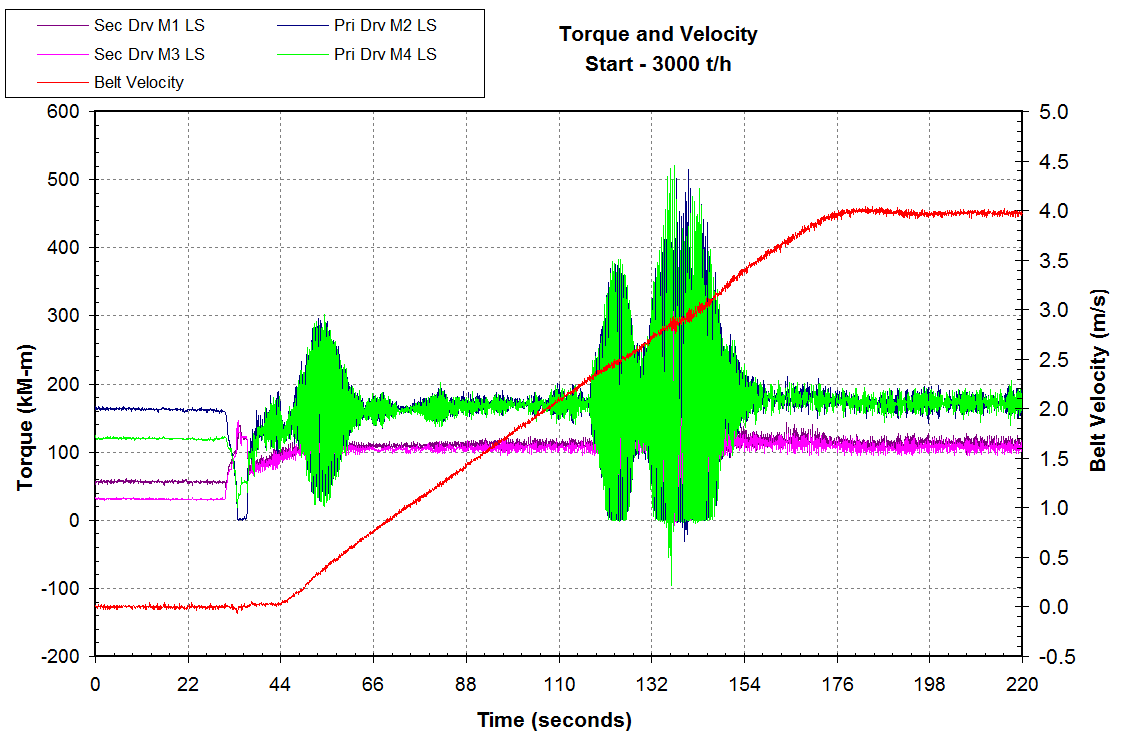
Figure 1. Vibration during starting – motors in load sharing control
Figure 2 zooms in on the torque of the primary drive during the second vibration. The torque varies from 0 kN-m to 540 kN-m which is almost 90% of the motor nameplate rating for that drive shaft. This figure shows that motor 2 (M2) and motor 4 (M4) are oscillating against each other. These two motors are both located on the primary drive shaft.
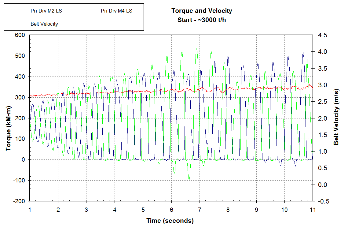
Figure 2. Zoom-in of primary drive torque of vibration during starting
The vibration was likely caused by a natural vibration mode of the motor and brake disk masses on the shaft.
The control of the motors was a master-slave relationship. The master VFD drive was controlled by a velocity feedback loop. The torque on the other three motors was set to load share with the master drive.
After careful analysis of the resulting measurements, and after performing several dynamic simulations, the authors recommended changing the control philosophy such that each drive was controlled individually using only speed control. It was predicted that this type of control would eliminate the vibrations occurring between motors on the same shaft. Figure 3 shows the motor torque and belt velocity after the control had been changed. Both the initial and secondary vibrations were almost entirely eliminated after the control change.
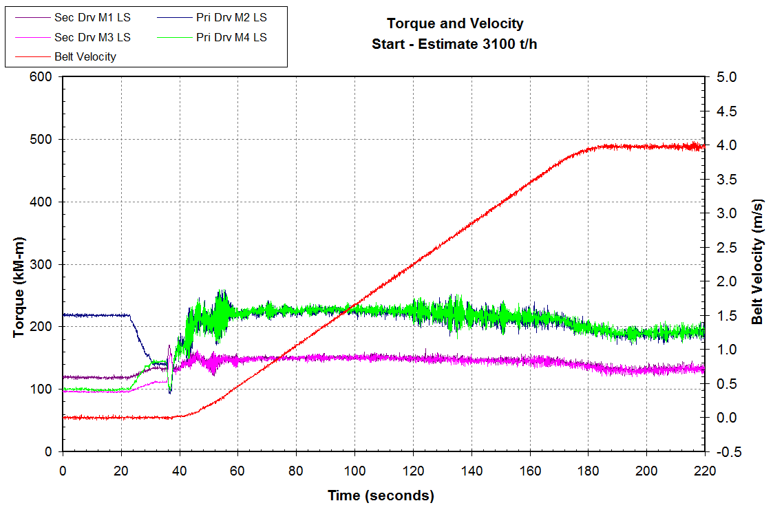
Figure 3. Motor torque and belt speed – motors in speed control
The design of the conveyor required a pre-tension step, which was not implemented in the control system. The belt should be held at 5% of full speed for a short time. This ensures the entire system is in motion before starting the main acceleration ramp. Pre-tensioning the belt provides smoother acceleration, lower belt tensions, and minimizes transient tension waves. Figure 4 shows the final start-up with the pre-tension step. The belt was fully loaded at 4750 t/h (which was the maximum available at that time). The belt started smoothly and without any problems. The system has now been in full operation for more than two years.
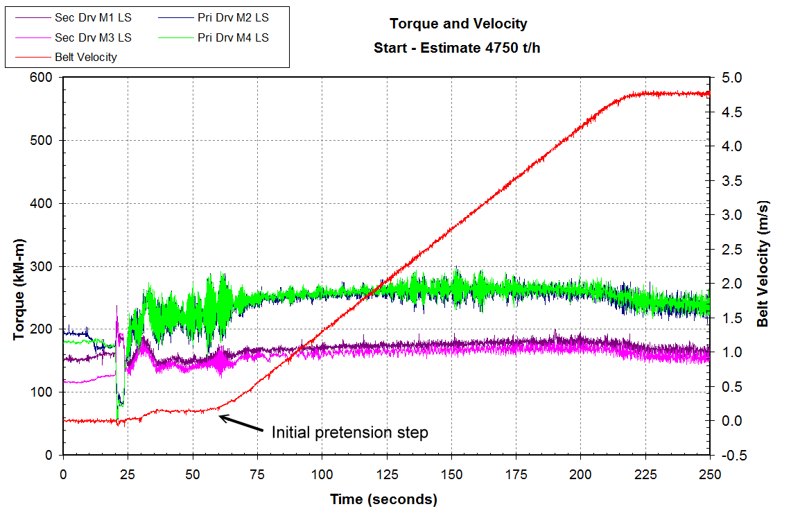
Figure 4. Motor torque and belt speed – start with pre-tension step
Even though the conveyor was equipped with VFD drive control, direct strain gage measurements were still crucial in accurately identifying and correcting the drive control issues. Combined with dynamic analysis and theoretical predictions, a stable starting control was implemented quickly and successfully.