The Ultimate Guide to Marine Shaft Power (Torsion) Meters
In an effort to optimize their operations, vessel owners and managers in the marine industry are moving more towards a “Smart” fleet, with various sensors providing the data needed to save fuel, reduce emissions, and extend maintenance intervals. One key piece of technology that helps do this are marine shaft power meters.
Shaft power meters help reveal the true mechanical horsepower, torque, speed, and thrust on a propulsion shaft. Their use spans decades in the marine industry with the technology on thousands of vessels.
With so many options for shaft power meters available in the market, the task of finding and selecting the right one can be daunting. In this guide, we help simplify the process by answering some common questions, including the different types of meters, the benefits you can expect once installed, selection considerations, and more.

Table of Contents
Frequently Asked Questions
How does a marine shaft power (torsion) meter work?
A marine shaft power (torsion) meter measures the real time torque (torsion), speed, and power output on a propellar shaft. When torque is applied to a shaft, a small amount of strain or “twist” occurs on the shaft surface. A shaft power meter measures this strain on the shaft with a sensor and wirelessly transmits the signal to a stationary receiver, which processes and calculates a torque value based on the mechanical properties of the shaft. The torque measurement is then combined with a speed measurement (usually measured with a built-in tachometer) to calculate power. Power is nothing more than a simple multiplication of torque, speed, and a factor depending on the desired units:
Power (Hp) = Torque (ft-lbs) x RPM / 5252
Power (kW) = Torque (Nm) x RPM / 9550
Because of the close relation between power and torque, the name “shaft power meter” is often used interchangeably with “shaft torque meter” or “shaft torsion meter”. Both torque and power can be important values depending on the application.
What are the different components of marine shaft power (torsion) meter system?
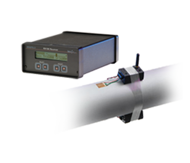
There are three primary components of a marine shaft power meter system: 1) A sensor 2) A transmitter, 3) A receiver. The sensors have the sole purpose of converting the twist on the shaft to an electrical signal. The transmitter energizes the sensor and wirelessly transfers the signal from the sensor off the shaft. Usually the transmitter (and sometimes the sensor) is embedded into a structure that is mechanically fastened to the shaft. The receiver is stationary (non-rotating) and within close proximity to the transmitter. The primary job of the receiver is to receive the signal from the transmitter, process the signal and output it in a data output format that is acceptable to the end user. In systems designed for long-term monitoring, the receiver also energizes the transmitter via an inductive link. By placing the hard-wired stationary receiver a close distance to the rotating transmitter, a magnetic field “induces” current into the circuitry that powers the rotating transmitter.


Figure 1. The TorqueTrak TPM2 shaft power meter from Binsfeld Engineering (left), A fuel flow meter (middle) and an engine control room display (right), commonly used in conjunction with a shaft power meter.
Marine shaft power meters are commonly used in conjunction with other accessory items as well. These include displays of the data for the engine control room or bridge, fuel flow meters, and/or cloud-based software to remotely access and monitor the data. Combining all of these elements together helps provide a full monitoring solution that enables real-time tracking of engine efficiency and other Key Performance Indicators over time.
What are the different types of marine shaft power (torsion) meters?
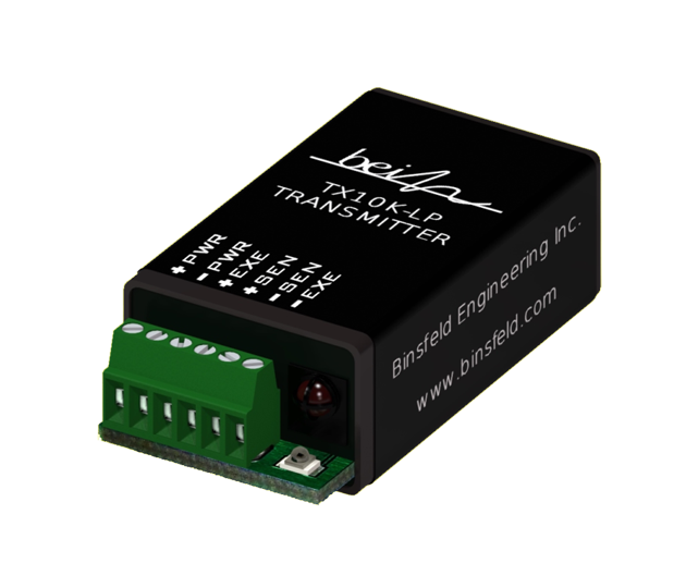
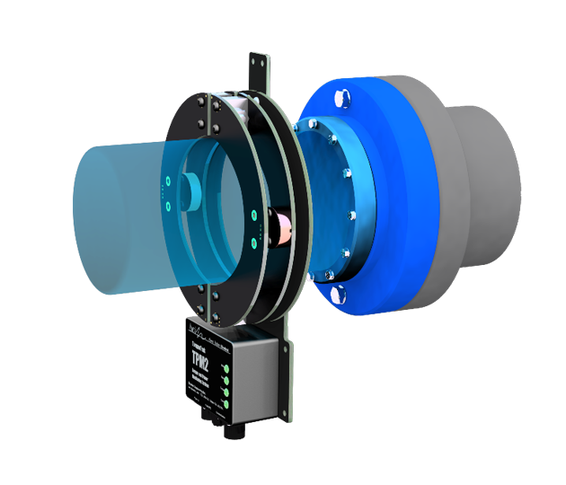
Marine shaft power meters generally come in two different categories – portable meters meant for short-term measurements during sea trials and permanently installed meters meant for continuous monitoring of torque and power. Portable meters are usually battery-powered and capable of being installed quickly on variety of different shaft sizes. Permanent marine shaft power meters are typically inductively-powered, allowing for continuous operation without the need to switch out batteries. They are usually specifically manufactured to the diameter of the shaft, although some manufacturers are starting to introduce modular systems that are attached to the shaft by chain links, allowing for easy interchangeability between shaft sizes. Due to the benefits they offer in terms of accuracy and fuel savings, the most popular shaft power meters in the marine industry are permanently installed systems.

Figure 2. A portable battery-powered system (left) and a permanently installed inductive system (right).
The primary difference between the various types of permanently installed shaft power meters is the method they use to sense strain (torque or “twist”) on the shaft. The most common methods include: optical, magnetic, and strain gages.
Optical
Optical systems rely on 2 bars that are bolted onto the shaft and aligned at a close distance from each other. A light is modulated between the two bars. As the shaft twists, the strength of the light changes which can be directly related to the amount of torque on the shaft. The advantage of these systems is that they are usually capable of detecting strain in multiple directions, meaning they can inherently measure torque and thrust with relative ease. However, this comes at the expense of decreased accuracy since the point of measurement is at a point removed from the actual shaft surface. The systems are also prone to picking up unwanted measurements (such as vibrations) and can be expensive.
Magnetic
In these systems, a magnetic band is strapped along the surface of the shaft. When torque is applied, the magnetic moments inside the shaft are reoriented, causing a magnetic flux to develop around the circumference of the shaft. The strength of the magnetic flux field is linearly proportional to the stress — and therefore, the torque — on the shaft, and the polarity of the magnetic field indicates the direction of torque. Magnetic field sensors positioned around the shaft determine the amount and direction of torque based on this flux. Systems that utilize this method tend to be relatively inexpensive and easy to setup. Getting bands to adhere perfectly to the shaft is virtually impossible, however, which induces a level of uncertainty into the measurements and decreases the overall accuracy.
Strain Gage
Strain gage- based sensors rely on a grid of metal foil bonded directly to the shaft. The instrumentation, i.e. transmitter, is connected to the gage and applies a voltage through the grids. As the shaft twists under load the grids or elements are stretched or compressed and change resistance which changes the voltage measured by the transmitter. (For more on how a strain gage works, visit our Blog: “What Is A Strain Gage and How Does It Work?”)
Strain gages are very precise, although more care needs to be taken during the installation process to ensure the gage is adhered and environmentally protected. Due to their accuracy, strain gages are typically considered the golden standard for propulsion shaft torque measurement, commonly referenced in a variety of international standards.
A summary table of the different methods is shown below:

Figure 3. Comparison of the three most common types of shaft power meters.
How much do marine shaft power (torsion) meters cost?
The cost of a marine shaft power meter depends on a variety of factors including shaft size, required accessories and whether or not installation and commissioning support is needed. The table below includes ranges for the most common expenses of a marine shaft power meter installation:

Figure 4. Most common expenses to a marine shaft power meter installation (as of January 1, 2020).
What are the benefits of using a marine shaft power (torsion) meter?
The key value proposition for any shaft power meter is that it provides an accurate, real-time, method for monitoring the shaft power on a vessel via a direct measurement of torsion on the propulsion shafting. Direct measurements of power can be 10-20% more accurate than engine estimations.
Fuel and power measurements provided by diesel engines originate from a theoretical “baseline” propulsion efficiency curve developed by the engine manufacturer. The baseline curve is theoretical and indirect, meaning the values are extrapolated from other measurements (such as electrical current). While the measurements may be somewhat accurate initially, their accuracy decreases over time. They do not take into consideration degradation of engine components over time, varying sea conditions, or the presence of inefficiencies such as hull fouling. To quantify this accurately, you need direct measurement. (More on this in our blog post Theoretical vs True Mechanical Torque).
Making vessel efficiency decisions based on inaccurate data leaves efficiency gains on the table. Implementing direct power measurements eliminates the guess work and helps vessel owners and managers make decisions that maximize efficiency.
More accurate measurements of vessel horsepower and torque have been shown to:
- Increase maintenance intervals by up to 50%. Through accurate measurements of real-time horsepower and/or other KPI’s such as Specific Fuel Oil Consumption, owners can delay maintenance on an engine until truly necessary.
- Reduce fuel costs by 5%, or more. This can be accomplished in several ways. Shaft torque/thrust measurements can help identify hull and/or propeller fouling at the on-set. Un-checked fouling has been shown to increase fuel burn by 5%. Additionally, monitoring shaft horsepower compared to a theoretical baseline efficiency curve established by the manufacture can help determine when inefficiencies are present.
A real world example of this can be found in the Harbor Tug case study in the PDF referenced in this blog.
What are common applications where marine shaft power (torsion) meters are used?
Testing should be performed during startup, shutdown and over the range of operating conditions. Time wave forms can be helpful to determine transmitted torque and overall alternating torque. Time wave forms can also be used to capture peak torque during a transient event such as synchronous motor startup or emergency shutdown (ESD) of a reciprocating compressor. Appropriate sampling rate needs to be used to capture the data. For example, if a telemetry system is set to 0-500 Hz range, then the data is typically sampled at 5000 Hz with the data acquisition (DAQ) system. Fast Fourier transform (FFT) is needed to determine the frequency content of the signal. By varying the operating speed and making a waterfall plot, the TNFs can be determined. A waterfall plot can also be made during a slow startup or unloaded coastdown.
There are a variety of applications where marine shaft power meters provide significant value in the marine industry. First of all, marine shaft power meters can be used to help troubleshoot propulsion problems. In these situations, specialized consultants with portable meters are brought in to characterize the performance of a propulsion system. A common problem involves a new build or retrofit vessel not achieving rated performance and it is suspected that either the propellar is designed incorrectly or the engine is not generating the horsepower it should. A power meter is used due to its high accuracy in obtaining the actual horsepower at the shaft to help determine whether the problem is with the engine or with the propellar. Another problem that occurs is the presence of excessive vibration on the driveline. In this situation, a torsion meter with a high sampling rate will be used to quantify the presence of torsional vibrations, which are a common cause of premature failures on rotating equipment.
Another common application for shaft torsion and power meters is demonstrating compliance to various regulatory and/or class certification requirements. A few of the most prevalent are as follows:

Figure 5. A plot of torsional vibration testing during a sea trial of an ABS class-certified vessel.
EU Common Fisheries Policy. Under European Commission Regulations fishing vessels are obliged to verify the declared engine power of fishing vessels to ensure compliance with the rules of the Common Fisheries Policy. The engine power of a fishing vessel (usually in kWs) is recorded for the Maritime Coastguard Agency (MCA) Registry and fishing vessel licensing. It is prohibited to fish with a vessel that is equipped with an engine whose power exceeds the one specified on the fishing license. Horsepower is commonly measured during a Bollard Pull Test.
MARPOL ANNEX VI – Measuring Emissions Standards. The Annex is a directive from the International Maritime Organization (IMO) that regulates the emissions of diesel engines and engine efficiency is a key performance measurement. The EEDI (Energy Efficiency Design Index) is a key measure that demonstrates compliance to this requirement. It measures the theoretical CO2 emission performance of new ships over 400 gross tonnes and is calculated from ship design and engine performance data. The Engine Efficiency (or Specific Fuel Oil Consumption) is commonly measured using a shaft power meter along with fuel flow meters, to demonstrate compliance to this requirement.
ABS Class Certification. Ships that are built to ABS standards are required to have torsional vibrations on the propulsion system analyzed. A shaft torsion meter is typically used to measure these torsional vibrations on the propellar shaft to ensure that there does not exist vibration modes that can cause premature failures.
How accurate are marine shaft power (torsion) meters?
We have already established that the primary benefit of marine shaft power meters is that they provide an inherently more accurate way of determining torque and horsepower than engine estimations but just how accurate are they? The short answer – usually 3%-5% (or better). The longer answer requires an explanation of the three primary sources of error: Instrumentation accuracy, calibration uncertainty, and assembly uncertainty:
- Instrumentation Accuracy
- The instrumentation accuracy between shaft power meters tends to be relatively consistent and quite precise (within .1-.3%). This is because the main source of this error are the electronics of the meters, which tend to be similar between meters. Of this error range, the most significant contributors have to do with the impact of temperature and non-linearity.
- Calibration Uncertainty
- Uncertainty in the calibration is the largest contributor to error in any shaft power meter. Shaft power meter calibration is the process of correlating an electrical measurement of a sensor to a physical torque or power value. The “Full Scale” output of the power meter (usually quantified in bits or volts), corresponds to a given torque and/or power value. This value is established by using an equation the relates the sensor to the shaft parameters (see figure below for an example). Error is introduced due to uncertainties in the inputs to the calculation (such as exact shaft diameter, gage factor, Poisson’s ratio, and modulus). Aside from physically testing the shaft material in a laboratory, there’s no way of knowing exactly what this will be for a given installation and it is possible the parameters are exact. This is why it’s referred to as uncertainty, as opposed to accuracy. Generally speaking, one can expect a 3%-5% error if these parameters are not known to a high degree of confidence.

Figure 6. A typical equation for calibration of a strain gage based shaft power meter.
3. Assembly Uncertainty
- Assembly uncertainty is error introduced by how far removed the shaft sensor is from the shaft surface. When a sensor is bonded to the shaft (such as with a strain gage), the amount of twist/strain on the shaft is sensed directly and the assembly uncertainty is essentially zero. When sensors are further removed from the shaft surface through a series of mechanical connections (such as with a bolt-on optical system), this error increases.
What needs to be considered when considering a marine shaft power (torsion) meter?
Selection of the appropriate marine shaft power depends on the specifics of the application. Below is a list of common considerations:
- Measurement Duration. If the measurements are for short-term testing (days), a battery-powered portable system should be selected. If measurements are needed long-term (months-years), inductively powered permanent systems should be explored. Some manufacturers also provide portable units with the option for inductive power, which is ideal for mid-term (weeks) testing.
- Desired Measurements. Most shaft power meters include shaft torque, speed, and power as default outputs. Thrust measurements can be included as an option for many systems, at an increased cost.
- Sensor Type. Although this was covered in a previous section, it is still worth noting that this is the main differentiator between shaft torsion meters. The selection requires carefully weighing the tradeoffs between cost, ease of install, and accuracy.
- Shaft Diameter. Marine shaft power meters have a minimum shaft diameter they can accommodate (usually no less than 152mm/6”). This becomes an important consideration for vessels with smaller shafts. If a diameter less than this is needed, the options become limited.
- Available Shaft Space. The amount of shaft available is an important consideration. The rotating sensor/transmitter assembly needs to physically fit on the shaft, while at the same time, allow for a robust signal path to the stationary receiving unit. Clamp-on optical systems usually require significantly more shaft space (>305mm/12”) than surface-mounted strain gage telemetry systems (152mm/6” or less).
- Desired Data Output. Shaft power meters come in a wide variety of data outputs, the most common being RS-485/MODBUS. Standard Analog Outputs are also available including 4-20 mA and +/- 10VDC. Digital signals tend to be more robust, less susceptible to noise, and more stable over time (reducing the need for re-calibration).

Figure 7. Smaller vessels, like this tug, have limited available shaft space. This makes it difficult for many shaft power meters to physically fit onto the shaft.
Shaft Power (Torsion) Meters from Binsfeld Engineering
Binsfeld shaft power meters include the TorqueTrak 10K, TorqueTrak 10K-LP, TorqueTrak Revolution, and TorqueTrak TPM2. The TorqueTrak 10K is a robust battery-powered, portable unit that has been used by consultants for over 10 years to provide reliable torque data from a shaft. It is compatible with the OPDAQ Field Test 2 Data Acquisition system. The TorqueTrak Revolution and TorqueTrak TPM2 are inductively-powered systems designed for continuous measurement of torque, speed, shaft direction, and power. All products are designed to be robust, easy-to-install, and highly accurate. More information on these systems can be found on their product pages:
TORQUETRAK 10K
Battery-powered shaft power meter meant for short-term testing
TORQUETRAK 10K-LP
Low-profile battery-powered shaft power meter.
TORQUETRAK TPM2
Inductively-powered shaft power meter for continuous monitoring – RS-422 and RS-485 output.
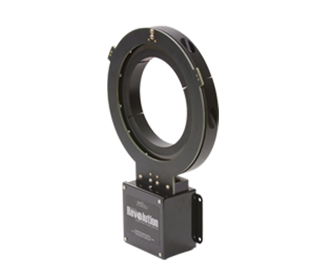
TORQUETRAK REVOLUTION
Inductively-powered shaft power meter for continuous monitoring – 4-20 mA analog output.