1. Desired Measurements
While all rotary torque sensors provide torque measurements, many can provide additional measurements as well. For example, if your application also requires a power output, then a speed measurement should be added. Some rotary torque sensors include an integrated speed measurement, while others require the speed measurement to be added separately.
For applications requiring a range of desired measurements, torque telemetry systems provide a distinct advantage. As they are compatible with a wide range of strain gage sensors, they are easily configured to suit your desired measurements, including Torque, Bending, Temperature, and Thrust/Axial Strain. Power can also be measured through the addition of a speed sensor.
2. Ability To Modify Shaft
One of the most fundamental questions that must be asked when selecting a rotary torque sensor is whether or not it is acceptable to modify or disassemble a driveline.
If shaft disassembly or modification is acceptable, then an in-line rotary torque sensor is a reasonable solution. These systems come pre-calibrated from the factory and are inherently resistant to adverse environmental conditions, making them ideal for many OEM applications.
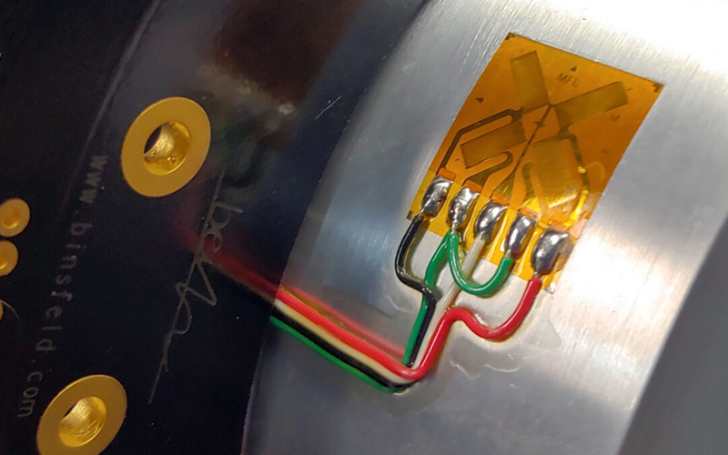
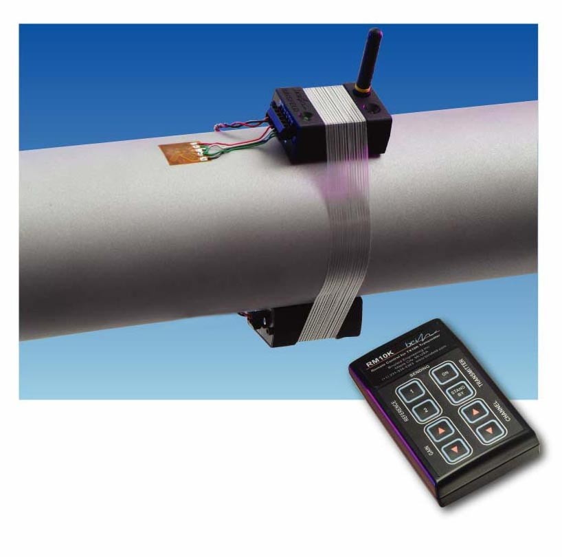
If shaft modification or disassembly is not feasible or desirable, a variety of rotary torque sensor solutions exist, including electrical power meters, bolt-on torque cells, or surface-mount torque telemetry. These solutions are ideal for applications where torque measurement is needed on a large piece of equipment that is already installed.
Learn more about how to measure torque on an existing shaft.
3. Testing Duration
Most rotary torque sensors are available in either temporary or long-term setups. Determining the duration of testing will help you decide which setup is best suited to your application.
For testing less than 48 hours in duration, battery-powered rotary torque sensors that rely on radio frequency data transfer for temporary torque measurements are ideal.
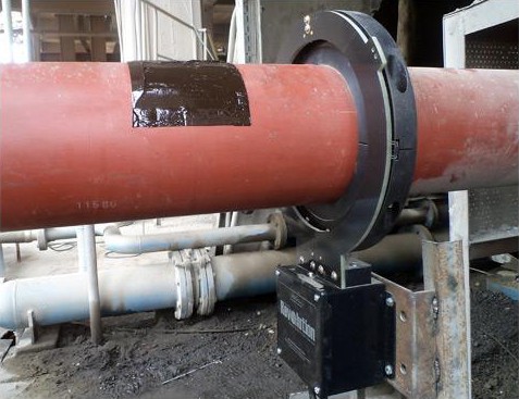
For long-term monitoring and testing, inductively powered permanent torque and power monitoring systems are the better solution.

4. Anticipated G-Force
Before selecting a rotary torque sensor, it is important to ensure that the anticipated G-force of your application does not exceed the recommended G-force of the system.
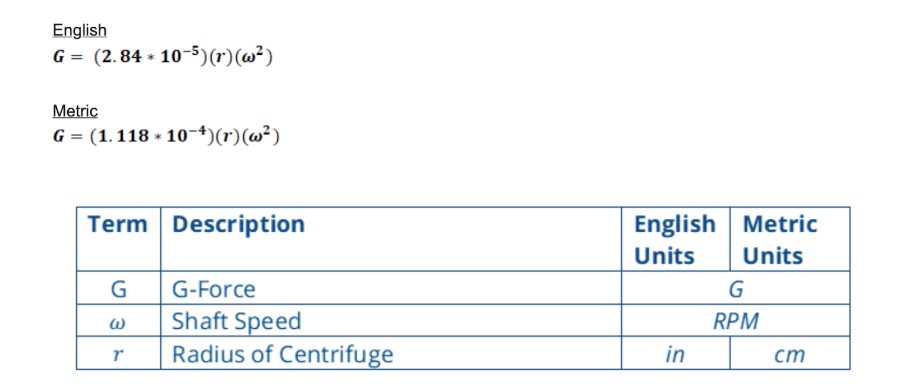
G-force is dependent on two things: shaft speed and shaft diameter.
The calculation of G-force is as follows. This equation is used to determine whether a torque measurement system can withstand the expected force in your particular application. Note that the radius (r) is often larger than the shaft radius since it includes the distance from the surface of the shaft to the furthest point on the torque measurement system.
For a detailed guide that includes an excel calculator of g-force and other fundamental equations, see the following: 5 Fundamental Shaft Torque Equations
5. Mechanical Properties of the Shaft
When selecting a rotary torque sensor, it’s important to understand the mechanical properties of the shaft — shaft diameter and material — to ensure that the rotary torque sensor you select is compatible with the size and type of rotating shaft you plan to measure.
Shaft Diameter
If the shaft diameter will vary between tests, then a system that is not diameter-specific is necessary. Traditional in-line torque transducers are usually designed to a specific diameter. Torque telemetry solutions like the TorqueTrak 10K or TorqueTrak 10K-LP are ideal here, as they can be mounted to a variety of driveshafts, regardless of diameter.
Shaft Material
Shaft material is equally important to consider when determining the method of installation and the method of calibration of your rotary torque sensor. If an in-line torque transducer is used, then usually the system comes pre-calibrated, and material is not a concern.
Anisotropic materials. Anisotropic materials like carbon fiber usually require a dead-weight calibration, where a known torque is applied via a mass of known weight being suspended at a known distance from the center point of the shaft.
Isotropic materials. Isotropic materials can be calibrated much easier through the use of a full-scale torque calculator. This method relates the mechanical properties of the shaft to the full scale output of the torque measurement system
Another key limitation related to the mechanical properties of the shaft is the ability to install the sensor onto the shaft. For torque telemetry systems, a strain gage is installed directly onto a shaft. Surface preparation requirements vary depending on the material the gage is to be bonded to. Ensure that you are prepared with the appropriate materials according to shaft material and the rotary torque sensor you select.


6. Desired Data Output Format
Rotary torque sensors output torque data using a variety of outputs, including analog and digital. You’ll need to select which data output format is best suited to your application.
Analog Output
Standard analog outputs include 4-20mA, +/-5VDC, +/-10VDC.
The primary advantage of an analog output is that it is easily synchronized with other similar analog signals. This is useful in the event that you are using multiple sensors to conduct a test. Data Acquisition Systems commonly accept analog output as well.
Digital Output
Common digital data outputs include MODBUS, RS-232, RS-485, and Ethernet. In some cases, manufacturers may specify less common outputs (such as RS-422) to allow for higher sampling rates with the benefits of a digital output.
The distinct advantages of digital outputs are that they are immune to electromagnetic interference, and can be transmitted for further distances without loss of signal. The outputs are also more accurate and stay more stable over time, because there is no digital to analog conversion necessary. This format is easily integrated into existing PLC systems.
7. Environmental Conditions
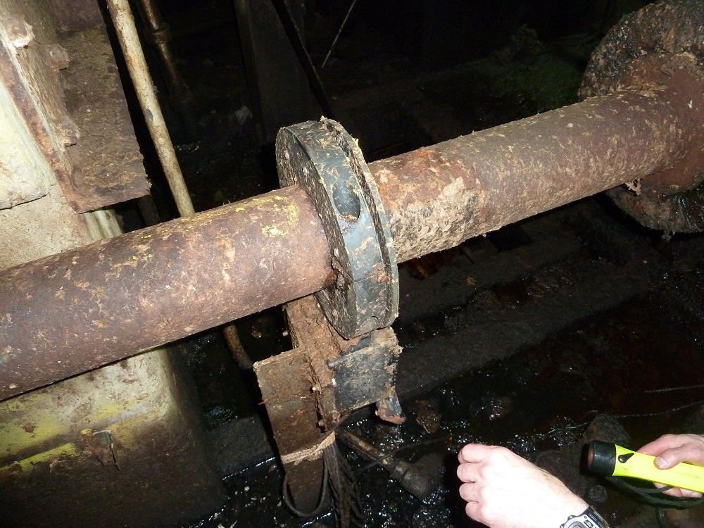
Another key consideration to make when choosing a rotary torque sensor is what type of environment the sensor will be used in. Will there be excessive debris and moisture? Or is your testing environment relatively clean? It’s important to understand any adverse environmental factors first, so you can take the proper precautions when installing your rotary torque sensor.
Some systems, like in-line torque transducers, come with inherently more environmental robustness. Most rotary torque sensors can also be sealed from the elements through the application of silicones and adhesives at points of ingress.
8. Surrounding Geometry
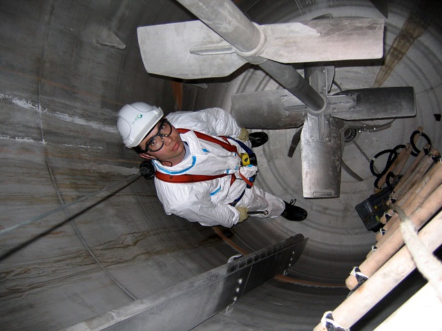
Consideration of surrounding geometry is important to ensure that there is no mechanical interference of the torque sensor, that there is a good location to mount the stationary portion of the system, and to ensure that there is minimal impact to the signal due to electrical interference.
When it comes to telemetry, inductive systems are sensitive to surrounding metal, while radio frequency systems are more sensitive to electromagnetic interference. Shielding and other post-installation efforts can be made to limit the impact.
There are a number of rotary torque sensor options on the market, each with different advantages and disadvantages depending on your unique application. By taking each of these eight steps into account before selecting a rotary torque sensor, you’re sure to choose the option that will provide the best solution for your application.
If you have more questions about rotary torque sensor selection, or if you’re still not sure which rotary torque sensor would be best suited to your application, talk to the experts at Binsfeld.


