Engineering Dynamics Incorporated (EDI) was requested to help perform an axial load test on a vertical water pump. Since commissioning, the pump experienced accelerated bearing and shaft wear. There was concern that problems might be due to up-thrust resulting in a bow in the vertical shaft. The pump is driven by a 250 HP induction motor with variable frequency drive (VFD) speed control. The thrust bearing is located at the top of the motor.
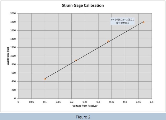
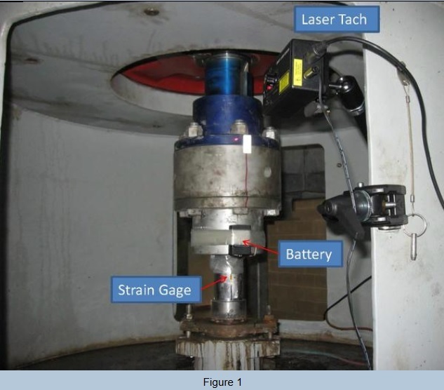
The TorqueTrak 10K telemetry instrument from Binsfeld Engineering and single-axis strain gages were installed on the shaft as shown in Figure 1. Calibration was done using hydraulic cylinders and a lifting plate under the coupling hub. The scale factor was experimentally determined based on the slope of the linear fit as shown in Figure 2.
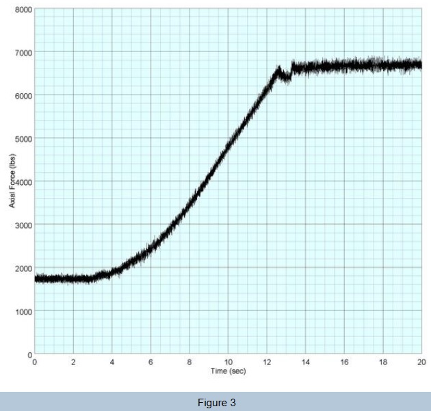
EDI’s data acquisition system was used to record all test data. The pump was started and brought to 100% speed. As shown in Figure 3, the axial force started at 1700 lbs (hanging weight of pump) and then increased to 6600 lbs. A positive reading indicates downward axial force. Therefore, no up-thrust condition was observed during startup.
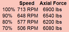
The pump was then tested from 70% to 100% operating speed. The measured force includes the thrust as well as the hanging weight of the line shafts and pump impellers. All values were positive and remained in the 6000 to 7000 lbs range as shown in the table below:
A final test was conducted with other pumps running at the station. The discharge valve was partially closed to increase discharge pressure and simulate rated head. The maximum axial force measured at this operating condition was 7600 lbs and compared well to the predicted down-thrust of 7500 lbs shown on the drawing.
Using the Binsfeld TT10K, up-thrust was ruled out as a possible cause of the bearing and shaft issues. Damage may have instead been caused by sediment in the river water being pumped by the station.