AUTOMOTIVE
DRIVE SHAFT TORQUE SENSORS
AUTOMOTIVE OVERVIEW
Binsfeld Engineering serves the automotive market with wireless torque sensor systems used in testing and development of cars & trucks. Our products are specifically designed to meet the space-constraints of the automotive market by offering low profile transmitters that provide reliable torque data from any rotating shaft.
DIAGNOSTICS/TESTING
- Measure the true mechanical torque on any rotating shaft (i.e. drive shaft, half shaft, axles)
- Optimize drive shaft design
AUTOMOTIVE DRIVE SHAFT TORQUE SENSORS
TORQUETRAK 10K
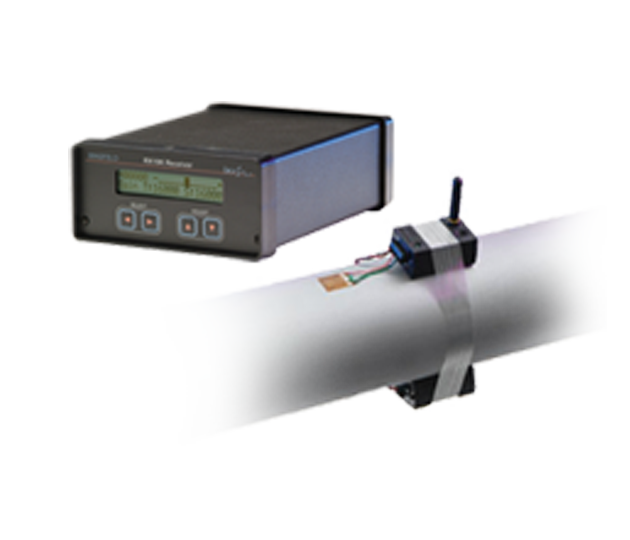
Temporary torque measurement system for rotating shafts. Battery-powered with robust reinforced housing.
TORQUETRAK 10K-LP
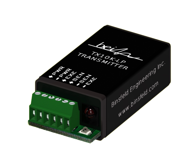
Low-profile temporary torque measurement system for rotating shafts. Battery-powered for short-term testing.
TORQUETRAK TPM2
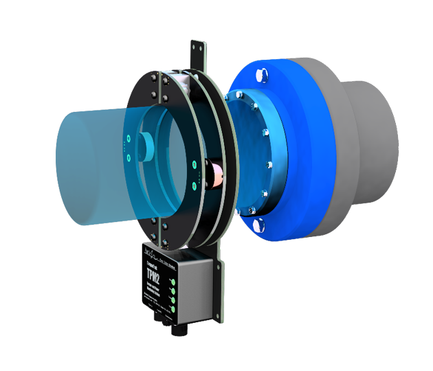
Sealed torque and power monitoring system with digital data output. Inductively powered for long-term testing.
AUTOMOTIVE CASE STUDIES
Driveshaft Failures on Hybrid Electric Vehicle
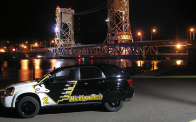
Mechanical engineering students working as part of the Michigan Technological University’s Challenge X Team were plagued by broken half shafts in the electric drivetrain of their Chevrolet Equinox hybrid vehicle. A resonant torque event was causing the failures that...
Torque Monitoring System Used in SAE Baja Buggy Development
SAE Baja is a challenging collegiate racing series hosted by the Society of Automotive Engineers where student teams design, build and compete off-road vehicles. Except for tires, rims, shocks and the engine, the teams must either customize or design and manufacture...
AUTOMOTIVE TECHNICAL TOPICS
HOW DOES A WIRELESS DRIVE SHAFT TORQUE SENSOR WORK?
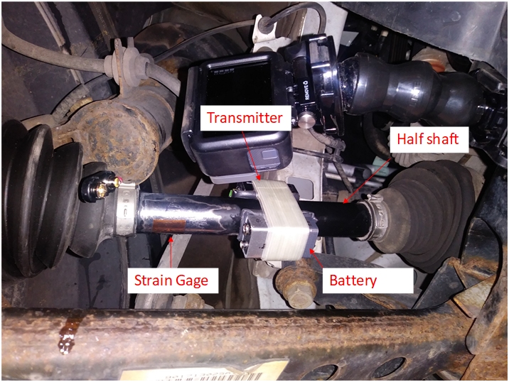
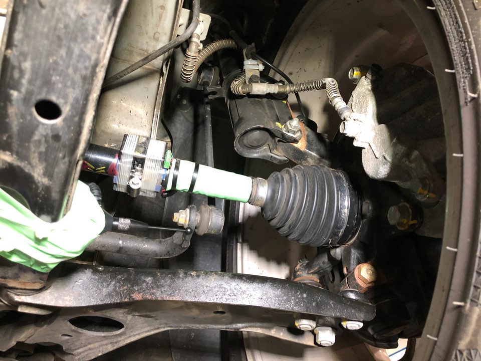
Drive shaft (or half shaft) torque can be measured by using wireless torque telemetry. A torque-sensitive strain gage is applied to the drive shaft and wired to a battery-powered transmitter. The drive shaft torque signal is transferred from the transmitter through radio frequency to a nearby receiver, then output to a data acquisition system. A typical set-up is shown below (Not pictured are the receiver and the data acquisition device).
