MARINE
SHAFT POWER METERS
MARINE MARKET BENEFITS, INFORMATION AND APPLICATIONS
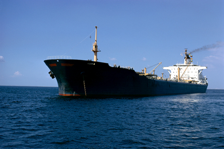
Binsfeld Engineering is proud to be a market-leader in the marine market, offering user-friendly and easily integrated torque and power measurement solutions. Whether our customers want to monitor vessel performance, diagnose the root cause of repeated component failures, or increase fuel efficiency, Binsfeld shaft power meters provide the data needed to get the job done.
PERFORMANCE MONITORING
- Reduce downtime by knowing when engine, propeller, gearbox, or bearing performance is degrading
- Initiate preventative maintenance or replace worn components only when needed
DIAGNOSTICS/TESTING
- Diagnose propulsion problems
- Figure out why hull efficiency has degraded (hull-fouling)
- Determine the root cause of an excessive torsional vibration on a propeller shaft
OPTIMIZE FUEL EFFICIENCY & REDUCE EMISSIONS
- Combine mechanical horsepower measurement with vessel speed and fuel consumption sensors to monitor fuel consumption and increase fuel efficiency
- Meet emissions requirements by optimizing fuel efficiency
RECOMMENDED PRODUCTS
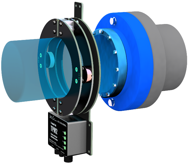
TORQUETRAK TPM2
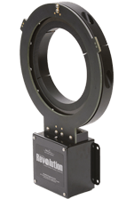
TORQUETRAK REVOLUTION
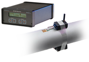
TORQUETRAK 10K

TORQUE MEASUREMENT SERVICES
VIEW PRODUCT DETAILS >
VIEW PRODUCT DETAILS >
VIEW PRODUCT DETAILS >
VIEW PRODUCT DETAILS >
TORQUETRAK TPM2
VIEW PRODUCT DETAILS >
TORQUETRAK REVOLUTION
VIEW PRODUCT DETAILS >
TORQUETRAK 10K
VIEW PRODUCT DETAILS >
TORQUE MEASUREMENT SERVICES
VIEW PRODUCT DETAILS >
TECHNICAL TOPICS
WHAT IS A MARINE SHAFT POWER METER?
A marine shaft power meter measures the real time torque (torsion), speed, and power of a marine shaft. The meter uses a strain gage to measure torque and a tachometer to measure shaft speed. Power is calculated by combining these two inputs (shaft speed and torque) into a simple equation.
WHAT IS ENGINE THRUST AND HOW IS IT MEASURED?
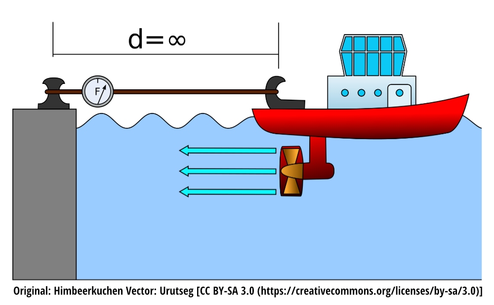
Engine thrust is the axial force exerted by an engine. This is realized as compression on the shaft. The most common way thrust is measured in the marine industry is through the Bollard Pull test. In this test, a boat is tethered to a post, and the engines are brought up to maximum power. A force/tension gage is used in-line with a rope to determine what the maximum Bollard Pull rating (or maximum towing weight) is.
The Bollard Pull test measures the cumulative pull force of all the propellers on a ship. If the thrust value for each of the ships individual engines is desired, then the thrust on each shaft can be measured by using a thrust pattern strain gage. Careful consideration for accuracy should be taken when using this method. Since the compressive displacement of a shaft is much lower than torsional displacement, the strain gage method is not as accurate (typically +/- 10%). An added advantage to using a shaft power meter during Bollard Pull Testing is that the true mechanical horsepower of the engine can be monitored, which can help identify if one engine is underperforming or help root-cause/prevent a failed Bollard Pull test.
WHAT IS HULL FOULING?
Hull fouling is defined as the buildup of organisms (plants, algae, barnacles, etc) on an engine hull. The buildup of these organisms causes the vessel to lose fuel efficiency (due to increased drag on the hull), can lead to the transfer of invasive species, and promotes corrosive damage on the hull. Hull fouling can be discovered by visual inspection or through the use of a shaft power meter. By comparing the output power to a calibrated baseline, ship performance monitoring can help identify if excessive drag is prevalent, which could indicate hull fouling.
APPLICATIONS
Torque Measurement Reveals Hull Fouling
| MACSEA’s new Hull Medic system detected hull fouling estimated to cost one USA Navy ship over $100,000 per month in extra fuel consumption. About 35% extra power, as measured by the Binsfeld Torque Meters, was required to maintain the ship’s operating speed with a fouled hull.
Hull Medic calibrates each ship’s propeller as a power absorption dynamometer, using the unique relationship between speed, propeller rpm, and shaft power. The TorqueTrak Revolution instrument from Binsfeld Engineering was selected to provide high-accuracy torque and power measurements on two ships as part of a Navy study to evaluate the effectiveness of alternate hull paint systems on fuel economy. Even small amounts of hull fouling like slime translate into large fuel penalties for active ships and the sooner the hull is cleaned, the more fuel can be saved. The fuel penalty of the Navy ship resulted from the ship sitting at birth throughout most of the warm summer months. With the help of the TorqueTrak Revolution instrument, Hull Medic detected the performance loss as soon as the ship returned to normal operations. |
 |
Ship Power Plant Protected by High Torque Alarm
| A ship management company that specializes in the transport of pleasure yachts had developed a new, efficient ship design. One of the features of the vessel was that the power plant was closely matched to the two 5,100 kW electric motors driving the propellers. Safeguarding the two diesel generator sets from overload was of concern.
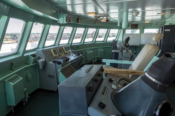
The TorqueTrak Revolution was selected to continuously monitor torque on the two propeller shafts. The torque signal was wired to the control panel on the bridge and would alert the crew when an overload condition was experienced. The auto-pilot control would reduce the ship’s speed in this event to prevent damage to the motors or power plant. |
 |
Ship Propulsion System: Navy Relies on Telemetry for Sea Trials
| Transfield Defence Systems, Melbourne, Australia – Catastrophic failure of the port drive shaft on the Australian naval frigate, HMAS Anzac, led to expensive dry-dock repairs. Potential variations in the newly installed drive system could invalidate computer controlled power, speed and trim settings for the vessel which utilized variable pitch propeller blades in addition to shaft speed to control power.
How could the Navy quickly test the repaired ship to verify equal load sharing between the port and starboard drives? Micro-Measurements strain gages and temporary diagnostic telemetry was installed by Binsfeld Testing Services. Torque measurements made during a two day sea trial confirmed equal load sharing and validated existing computer performance settings. |
 |
'Ghost' Torque Captured Onboard Navy Ship
Rolls-Royce Marine NA in Old Saybrook, Connecticut was asked by the US Navy to investigate a report of rudder post binding on one of their ships. Although none of the affected equipment was manufactured by Rolls-Royce, the Navy sought the Marine Engineering Services of Rolls-Royce due to a long history of providing successful problem-solving services. This problem was tricky to identify through normal means and only seemed to occur during long transits and did not manifest itself while the ship was in port. Because the ship normally operated on short near-costal missions, the task of replicating the problem was particularly difficult.
The Rolls-Royce Engineering for Services Team prepared a plan to simulate a transatlantic crossing and employed the use of Binsfeld’s TorqueTrak TT10K system to provide continuous real time monitoring of the force being applied to rotate each of the two rudders in an effort to capture the “ghost torque” when it reoccurred.
After installing a Micro-Measurements torsion sensing stamp and associated data collection equipment on each rudder post, a twenty four hour test schedule was initiated. While underway, the ship maneuvered continuously (swinging her rudders) for over twenty hours with no apparent issues.
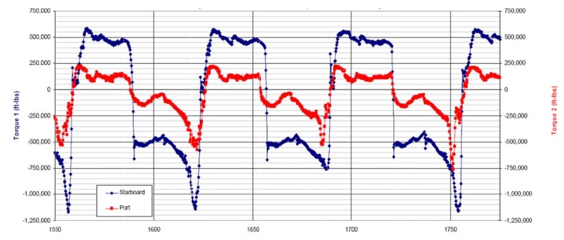
With only a short time left in the test program we observed a small spike in the torque necessary to move one of the rudders. Over time, the torque required to move the rudder started to climb. By the time the testing was completed the torque necessary to move the affected rudder was over double that of the other rudder (exceeding one million foot pounds of force). The evidence of the ‘ghost torque’ was now conclusive and had been captured electronically for playback and analysis ultimately resulting in determining the cause of the rudder binding and successful correction of the problem.
The figure below shows a data clip from the hours of data captured by the TT10K system. The excessive torque required to move the affected rudder as it cycled from port to starboard is shown in blue.
Steam Engines: Determine Horsepower Demand
| The S.S. Badger is a passenger and vehicle ferry that has been in service since 1953. Currently, she shuttles across Lake Michigan between Manitowoc, Wisconsin and Ludington, Michigan. What makes her unique is this: she is the very last coal-burning steamship in service in North America.
Due mostly to environmental regulations, burning coal on the Great Lakes has become prohibitively expensive. The owners, Lake Michigan Carferry Service, are investigating whether to replace the 60 year old coal-burning steam engines with modern engines. But how much Power is needed from the new engines? The old steam engines were rated (60 years ago) at 3500 Hp each, 7000 Hp total for the vessel. Does the ship need all that Power? How much Power does she use now during normal operation and the routine crossing of Lake Michigan? These questions must be answered now before the new engines are specified. Binsfeld Engineering and OpDAQ Systems were hired to make live measurements of Torque, RPM & Power on the two propeller shafts while underway, using the TorqueTrak 10K instruments plus Op-Torq Field Test data acquisition system. The results were quite interesting and exactly what Chief Engineer Chuck Cart had expected. Normal Operating Power for the steam engines was about 1700 Hp per shaft, 3400 Hp total. Max Power output of the engines was about 2500 Hp per shaft, 5000 Hp total. Conclusion: 7000 Hp is not needed for the new engines. 5000 Hp will be more than sufficient.
|
 |
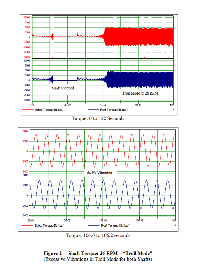
Marine Propulsion System Upgrade Trials
LamaLo Technology Inc. (LLT) commonly conducts marine propulsion shafting vibration and powering measurements in support of new construction, propulsion upgrades, and troubleshooting. Binsfeld TorqueTrak 10K telemetry systemsare used to measure the shaft torque. Measurements are displayed in near-real time on the lap top computer, so an assessment of the vibration severity and delivered shaft power on-site.
A recent project involved a vessel that was built in 1969. The propulsion system had two fixed pitch propellers, each driven by a diesel engine. The vessel had gone under various refits since construction, including adding sponson tanks in 1976 and new diesel engines in 1980. In 2010/2011, the vessel had a refit conducted, which included upgrades to the shafting and propeller, and the addition of a bulbous bow and a bow thruster. The vessel service speed was 11.5 knots prior to the upgrade.
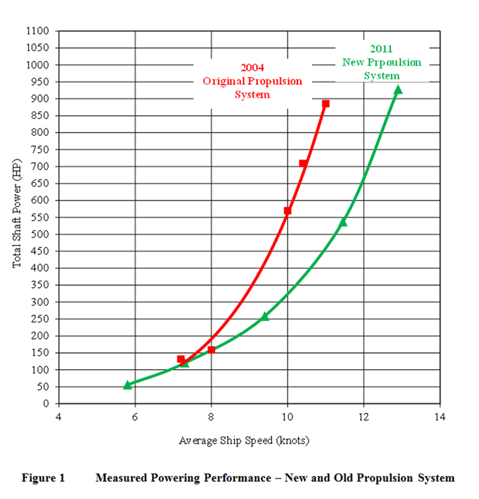
The primary objective of this project was to measure and report on the powering performance and shafting torsional vibration characteristics during sea trials. The results of the measurements indicated that a speed of 12.9 knots was achieved with a total shaft power of 928 HP at a shaft speed of about 296 RPM. About 15% more power was developed with the new propeller at the same shaft speed. Excessive torsional vibrations were measured at low shaft speeds, resulting in gear tooth backlash. The minimum shaft speed was set to 60 RPM based upon the torsional vibration measurements. Figures 1 and 2 illustrate results of the measurements.
For this marine propulsion system, the TorqueTrak 10K telemetry instrument was used to verify and demonstrate the associated benefits of a recent system upgrade, namely, an increase in vessel speed at less power and less fuel usage. That is exactly what the designers had hoped to see. At the same time, the TorqueTrak 10K was used to check torsional vibration in order to put corrective measures in place.
Setting Engine Maximum Power Output
When power is money, using Binsfeld TorqueTrak TT10K torque meters can assist engine manufacturers to set maximum power output.
A tug barge owner, operating in Alaska, had to re-fit his tug propulsion system in order to comply with environmental regulation. In his case, fuel consumption was not an issue. The main goal was to get maximum power on propulsion shafts.
By installing Binsfeld’s TorqueTrak TT10K torque meter, a Micro-Measurements strain gage, an RPM module, and software analysis, it was possible for the shipyard to examine, in real time, the engine Horsepower. To monitor the tug bollard pull test, the shipyard requested a third party. On request, Binsfeld certified product installer (OpDAQ Systems) was on site for the equipment installation and to provide quality measurement and monitoring.
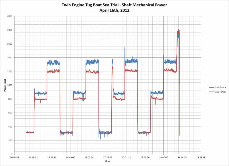
After the first day of bollard pull test, the ship-owner representative was not satisfied with the engine power. On the second day, the engine manufacturer had a new engine setting program ready to download in order to get more fuel in the injection system. Following the new setting, the ship owner request for more power was granted, but not without waiving the warranty. This story does not tell the tug fuel consumption at engine power maximum output!
This case study has been provided by our partner, OpDAQ Systems in Rimouski, Québec, Canada., Tel: 418-727-5753 / Web: www.opdaq.com
Damaging Torsional Vibration Identified and Eliminated
The Torsional Vibration Calculation (TVC) showed no abnormalities, but obviously something was not right. A deeper investigation was required. Two TorqueTrak 10K instruments were installed, one on each propeller shaft and the true dynamic torque on the shafts was measured.
Testing revealed the presence of significant oscillating torque (torsional vibration) when the Controllable Pitch Propeller (CPP) was at 50 to 60 percent. The torsional vibration was significant enough to cause the coupling damage.

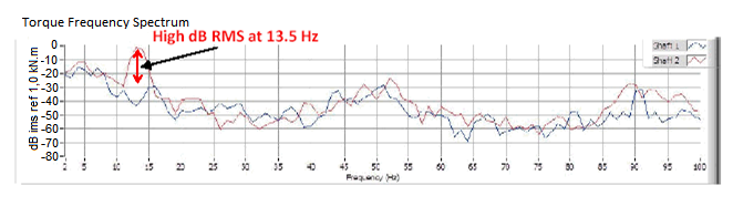
Another TVC was performed using a coupling with different shore hardness. The starboard side coupling was replaced with a 50SH element while keeping the port side as it was originally. New measurements were made with the TorqueTrak 10K instruments. This time the report showed a surprising difference.
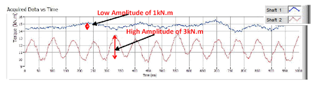
For the starboard shaft the high vibratory torque that was previously present no longer existed. The higher shore hardness made a big difference. Both coupling elements were replaced with new ones rated at higher shore hardness, 60SH. This greatly reduced the torsional vibration strain and eliminated the breakage of couplings.
Torsional Vibration on Tanker Shaft
| Hagen Andersen, DNV (USA) Inc., uses the TorqueTrak 10K telemetry instrument from Binsfeld Engineering to perform true mechanical Torque & Power measurements on marine propeller shafts. Shown below is a recent case study.
DNV was contracted by a United States ship owner to perform torsional vibration measurements on the main propulsion system, specifically on the propeller shaft of an oil tanker. The ship owner’s concern was related to the torsional vibration damper on the main engine. They needed to know if the damper was functioning properly. DNV was tasked with getting torsional vibration measurements from the intermediate shaft which would show the effectiveness of the damper. They did so by using the TorqueTrak 10K in conjunction with a Micro-Measurements strain gage and DNV’s Nauticus Torsional Vibration Software. This combination allowed DNV to accurately measure the torsional vibrations within the ship’s propulsion system and compare the measurements with the predicted values from the analysis carried out using the Nauticus Torsional Vibration Software. Using this combination DNV determined that the torsional vibration levels were acceptable and the damper was operating satisfactorily. Vessel data: Type of vessel : Multi Product Carrier DWT : 42,000 Main engine MCR power: : 12,500 kW Main engine MCR speed: : 90 RPM Propeller type: : 4 Bladed Fixed Pitch Propeller diameter: : 7,400 mm
|
 |
CLIENTS

EDISON CHOUEST OFFSHORE
ROLLS-ROYCE MARINE
BOLLINGER SHIPYARDS
CANADIAN COAST GUARD
GROUPE OCÉAN
EDISON CHOUEST OFFSHORE
ROLLS-ROYCE MARINE
BOLLINGER SHIPYARDS
CANADIAN COAST GUARD
GROUPE OCÉAN
BINSFELD ENGINEERING INC.
Maple City, MI 49664 USA
  231.334.4383
  Contact Us
  ISO 9001:2015 Certified
TORQUETRAK
Binsfeld’s Torque Measurement Systems measure true mechanical torque and power on rotating shafts. We also offer consultation, strain gaging and installation services.
Binsfeld’s Rotary Temperature Transmitter Systems provide accurate and reliable temperature control on heated godets and calendars. We also offer design and OEM services.
TORQUETALK NEWSLETTER
Sign-up to receive featured application stories, relevant news, tips, and new product release information for our torque measurement products.