STRAIN GAGE INSTALLATION
STRAIN GAGE INSTALLATION & FAQ’S
STRAIN GAGE INSTALLATION
Strain gage installation is a delicate process that depends on a variety of factors including but not limited to shaft material, geometry, surface condition, and type of strain gage. Although the process is involved, with careful attention, most of our customers are able to complete the installation themselves by following step-by-step instructions. Binsfeld offers Strain Gage Installation Services for those that would prefer we take care of the install for them.

TYPICAL INSTALL – SOLID STEEL SHAFT WITH TORQUE PATTERN GAGE
1. PREPARE SHAFT SURFACE:
- Remove paint and other coatings; degrease as necessary.
- Rough sand with 220 grit paper then polish with 400 grit paper.
- Finish sanding with 400 grit paper and M-Prep Conditioner.
- Rinse with M-Prep Conditioner.
- Rinse with M-Prep Neutralizer and wipe dry.
2. MARK SHAFT SURFACE FOR STRAIN GAGE ORIENTATION AND ALIGNMENT.
- The strain gage should be installed flat and square to the axis of the shaft. For a straight reference line square to the axis, wrap a piece of paper around the shaft, align the edges and then mark or etch the straight reference line onto the shaft.
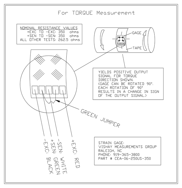
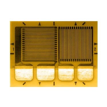
- Part # CEA-06-250US-350 is a common torque-pattern strain gage.
- Remove strain gage from package.
- Apply cellophane tape to top side of gage. Use the tape as a “handle.”
- Tape gage in place on the shaft using reference marks on shaft and gage for alignment.
- Lift one end of tape and “hinge” back to expose bottom of gage.
- Apply an even, thin layer of catalyst to bottom side of gage and let dry.
- With the gage/tape still hinged back, apply bead of M-Bond 200 Adhesive where the tape meets the shaft surface. (M-Bond 200 is a special Cyanoacrylate which has been pretested and certified for use in bonding strain gages – manufactured by Vishay Measurements Group.)
- Using Teflon film or equivalent as a non-stick barrier between your thumb and the adhesive, press the gage/tape to shaft surface with single rolling/wiping motion of the thumb.
- Apply thumb pressure for one minute, followed by a minimum two-minute wait before removing the cellophane tape. Bond strength increases rapidly during first five minutes.
- Discard Teflon film and carefully peel back cellophane tape from the strain gage.
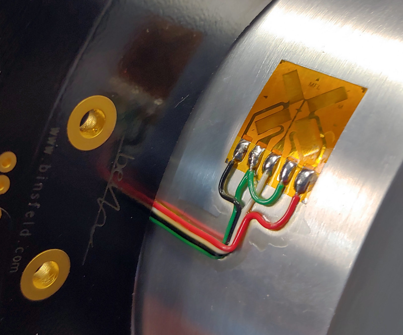
- Tin with solder the solder pads of the strain gage plus the lead wires. Attach lead wires to solder pads.
- Clean solder joints with rosin solvent.
- For waterproofing – Apply polyurethane coating to strain gage and solder joints.
- For mechanical protection – Cover the gage with butyl rubber or equivalent.
- For electrical shielding – Cover the strain gage and lead wires with aluminum tape or equivalent.
- M-Coat J from Vishay Measurements Group is a two-part polysulfide liquid polymer compound for environmental protection of strain gage installations. When fully cured, it forms a hard rubber-like covering that provides an effective barrier against water and many other fluids. The tough coating also protects installations from mechanical damage.
INSTALLATION CONSIDERATIONS FOR IRREGULAR SHAFT MATERIALS & GEOMETRIES
If installing the strain gage on a material other than steel, then the surface preparation requirements will be different from the steps listed above. See Vishay’s Strain Gage Surface Preparation Guide for detailed instructions for different materials.
-
Installing a strain gage on carbon fiber for torque measurement is not recommended. Installing the strain gage on carbon fiber shaft material presents a difficult challenge – calibration. Calibrating the torque/strain measurement is not possible using a mathematical equation because carbon fiber is not “homogeneous and isotropic”, as are steel, aluminum and common metals. The carbon fibers are oriented in the shaft, so torque/strain sensitivity at 0° does not necessarily equal sensitivity at 90°, for example. Instead, a metal portion of the shaft (such as a coupling) should be used.
- Welded Seams may induce some non-linearity. If it is an extruded section then the output should be closer to linear. Placing the gages on the faces that do not have the seam would be best.
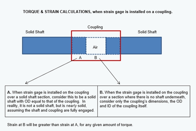
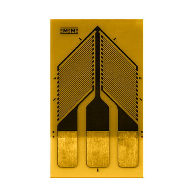
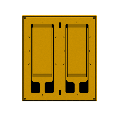
- For couplings, a chevron strain gage that cancels bending is recommended with the following considerations (See Figure 1).
- For tapered shafts, use the same gage as would be used on a normal shafts. For calculations, use the average diameter at the gage location.
- A typical keyway (i.e. one that is not unusually deep or wide) has a negligible effect (less than a few percent) on the accuracy of the torque measurements presuming the gage is mounted 180° from the key slot
HOW LONG DOES A STRAIN GAGE LAST AFTER IT IS INSTALLED?
A strain gage can remain valid for years, especially if it is protected with M-Coat J protective coating. We recommend this coating be used in addition to the Polyurethane that is part of a standard strain gage install. See Training Videos for how to apply M-Coat J coating.
CAN A STRAIN GAGE BE RE-USED?
No. Once the strain gage is glued to the shaft, it has been “consumed.” It cannot be removed and installed in a second location. This is due to the sensitivity of the gage. Gages can easily become damaged during removal, and any remaining glue can introduce artificial stresses in the gage, ultimately leading to inaccurate strain measurements.
WHICH STRAIN GAGE IS BEST FOR MY APPLICATION?

MEASURE TORQUE
MEASURE TORQUE-INSENSITIVE TO BENDING STRAIN
MEASURE AXIAL STRAIN THRUST, COMPRESSION OR TENSION
MEASURE BENDING – INSENSITIVE TO TORQUE & AXIAL STRAIN
PART # CEA-06-250US-350 >
PART # CEA-06-187UV-350 >
PART # CEA-06-250UT-350 >
PART # EA-06-250MQ-350 >
MEASURE TORQUE
PART # CEA-06-250US-350 >
MEASURE TORQUE-INSENSITIVE TO BLENDING STRAIN
PART # CEA-06-187UV-350 >
MEASURE AXIAL STRAIN THRUST, COMPRESSION OR TENSION
PART # CEA-06-250UT-350 >
MEASURE BENDING – INSENSITIVE TO TORQUE & AXIAL STRAIN
PART # EA-06-250MQ-350 >