A Beginner’s Guide to Torsional Vibration Analysis
Of the vast array of torque measurement applications, one of the most intriguing is the measurement of torsional vibration. Torsional vibration measurements allow engineers to better understand the dynamics of their rotating equipment, enabling them to troubleshoot and/or validate performance. While this remains a largely specialized field, the concepts behind torsional vibration measurements are relatively straightforward and can be mastered by those with a basic understanding of the principals of vibration and how it correlates to equipment performance. With a better understanding of the reasons and methods to measure torsional vibration, the right instrumentation, and a helpful partner, you will become better positioned to make the decisions you need to decrease downtime and increase productivity. In this guide, we explain the basic concepts behind torsional vibration analysis including what it is, how to do it, and why it’s important.

Table of Contents
Frequently Asked Questions
What is torsional vibration?
Torsional vibration is angular vibration that occurs about the axis of a shaft. It is different than lateral vibration (which occurs in the radial direction) and axial vibration (which occurs along the shaft length). Torsional vibration involves speed fluctuations of various components and the twisting of shaft sections while the machinery is rotating.
Excessive torsional vibration can lead to failures of such items as shafts, couplings, fans, gears, engine dampers, and compressor oil pumps. These failures typically occur at a 45-degree angle to the shaft axis. Unfortunately, torsional vibration problems may not be apparent until after a failure occurs.

Figure 1. A cracked coupling due to excessive torsional vibration on VFD motor – ID fan [Courtesy of Engineering Dynamics Inc (EDI)]
What is torsional vibration analysis (TVA)?
Some people use the term torsional vibration analysis (TVA) to mean taking measurements. However, TVA more commonly refers to calculations performed with a computer program. Some industries such as oil and gas require TVA of new equipment per American Petroleum Institute (API). For example, mass-elastic data are used to calculate torsional natural frequencies (TNFs) and mode shapes, interference diagram, and forced response. Other industries such as municipalities may specify analysis in the design stage and testing during commissioning of water pumps.
Why is torsional vibration analysis & torsional vibration testing important?
Torsional vibration and testing may be necessary to determine separation margin from torsional natural frequencies (TNFs) or to verify previous calculations. If a torsional problem is found, the system may need to be modified. Once the mass- elastic model has been normalized to match the measurements, the torsional vibration analysis software can be used to evaluate any proposed solutions. To avoid torsional resonance, this may require changing the torsional stiffness of the coupling, the inertia of a flywheel, etc.
Torsional vibration measurements help engineers increase the reliability and safety of rotating equipment.

Figure 2. A vibration consultant measuring torsional vibration [Courtesy of ED)]
What equipment is needed for torsional vibration testing?
An accelerometer is used to measure lateral vibration, but special equipment is needed to measure torsional vibration. Torsional vibration can be measured using a torsiograph, encoder, or laser vibrometer. These devices will determine angular oscillation and/or angular velocity. Some people have even detected high torsional of a disc pack coupling vibration using a simple strobe light to view warping or “pop canning” of the elements during operation.
Telemetry systems (such as the TorqueTrak 10K) can be used to measure shear torsional strain. The torsional strain value can then be converted to stress and/or torque by knowing the geometry and material properties of the shaft section. For example, the transmitted torque can be determined from the average value of the time wave form. The alternating torque can likewise be determined from the time wave form. The peak-to-peak value would be maximum – minimum. The alternating torque is usually expressed as zero-peak or (maximum-minimum)/2.
These measured torque levels can then be compared to the rating of a coupling.
The optimal location for measurement depends on the torsional mode shape. For alternating torque, it is best to measure near a node crossing. For the first torsional natural frequency (TNF) this is usually near the coupling. Whereas a torsiograph, encoder, or laser vibrometer should be used near an anti-node (point of maximum angular oscillation).
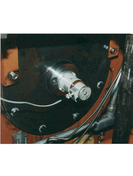
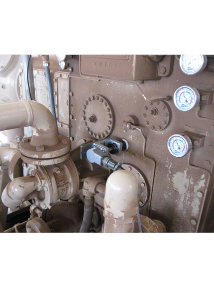

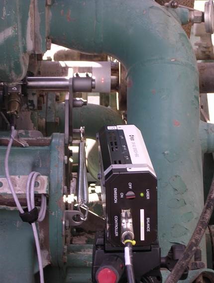
Figure 3. From left to right – A torsiograph, an encoder, a telemetry system and a laser vibrometer, all used to measure torsional vibration [Courtesy of EDI]
What are common applications that require torsional vibration analysis & torsional vibration testing?
Situations where torsional testing may be required could include the following:
[Excerpt from 2009 Turbomachinery Paper “Prevention of Torsional Vibration Problems in Reciprocating Machinery” by T. Feese and C. Hill]
- If a failure of a component occurs, testing of the repaired system is recommended to investigate the cause(s).
- If a system poses unusually high risks to life, other machinery, or plant processes, testing should be performed to ensure reliable operation. This could include a prototype machine or an existing model operating at higher speeds or pressures than previously
- This could include systems with torsionally soft rubber couplings and/or wide speed ranges or operating If many assumptions had to be made in the torsional analysis phase due to lack of drawings and technical information, testing should be used to confirm the results.
- Newly designed systems that will be mass produced should be tested under It is much easier to correct a problem with an initial unit at the factory than it is to retrofit many units that have already been shipped to customers.
- Systems that have been modified or put into a different service, such as re- staging and/or changing operating conditions, should be re-analyzed or
- Many municipalities have specifications that require torsional vibration testing of new units by a professional
In industrial applications, the most common equipment where torsional vibration testing is important is with variable frequency drive (VFD) motors driving large inertia fans and reciprocating engines/compressors. For VFD’s, problems can occur due to tuning of the drive. Reciprocating engines and compressors can have much higher excitation than rotating machinery. Having a wide operating speed range will be more likely to encounter a torsional resonance.
In marine applications, torsional vibration testing is often required on propellar shafts to troubleshoot propulsion problems or to quantify excessive vibrations predicted in a computer torsional vibration model. Torsional vibration measurements are often required to meet meet certain classifications for new build or re-powered ships. Section 7.9 of the ABS Guidance Notes on Vessel Vibration highlights: “If measurement is conducted as per 4-3-2/7.5.8 of the ABS Steel Vessel Rules, torsional vibration measurements are to be taken either at the free end of the propulsion machinery, using a suitable torsional vibration transducer, and/or on the main shafting, using strain gauges. Alternatively, depending on the system characteristics, a mechanical torsiograph, driven from a suitable position along the shafting or free end, may be used for this purpose. “

Figure 4. A waterfall plot indicating a torsional natural frequency at 20 Hz. [Courtesy of EDI]
How is torsional vibration testing performed?
Testing should be performed during startup, shutdown and over the range of operating conditions. Time wave forms can be helpful to determine transmitted torque and overall alternating torque. Time wave forms can also be used to capture peak torque during a transient event such as synchronous motor startup or emergency shutdown (ESD) of a reciprocating compressor. Appropriate sampling rate needs to be used to capture the data. For example, if a telemetry system is set to 0-500 Hz range, then the data is typically sampled at 5000 Hz with the data acquisition (DAQ) system. Fast Fourier transform (FFT) is needed to determine the frequency content of the signal. By varying the operating speed and making a waterfall plot, the TNFs can be determined. A waterfall plot can also be made during a slow startup or unloaded coastdown.
Using Torque Telemetry for Torsional Vibration Analysis
As discussed, telemetry can be an invaluable tool for torsional strain measurements in torsional vibration analysis. The recommended configuration from Binsfeld Engineering is the TorqueTrak 10K telemetry unit with the OPDAQ Field Test 2 data acquisition system. The TorqueTrak 10K will provide the torsional measurements and the OPDAQ Field Test 2 data acquisition system will store the data on a PC using a built-in high-frequency mode that enables data capture at rates up to 2400 Hz. The user could then do a frequency analysis (FFT) on the data to determine the resonant frequencies where torsional strain is the greatest and, if necessary, implement a corrective action to minimize that torsional strain to a safe level.

Figure 5. Torsional vibration testing kit from Binsfeld Engineering.
Most often, the amplitude of the torsional vibration data is directly related to shaft speed (RPM). Torsional vibration causes premature wear and sometimes even damage to equipment, such as bearings and couplings. Therefore, it should be identified and de-tuned, if necessary. On big equipment, torsional vibration can be de-tuned by placing extra inertia on the shaft at a specific location. On ships, there is what is known as the “barred speed range.” This is a shaft speed (RPM) range where torsional vibration is the greatest and the ship Captain knows to pass through the “barred speed range” as quickly as possible.
Additional examples of torsional systems where Binsfeld’s TorqueTrak 10K telemetry system has been used for torsional vibration analysis and testing include:
- VFD motor driving various types of fans (ID, FD, and MVR).
- VFD motor driving centrifugal compressor for gas pipeline
- VFD motor driving pumps for fresh water and wastewater plants
- Reciprocating compressors systems driven by motors or engines
- Belt driven multiphase compressor for oil and gas industry
- VFD motor driven winder at paper mill
- VFD motor driven 310-ton crane at nuclear facility
- Engine driven firewater pumps
- Motor – gearbox – reciprocating compressor system at refinery
- Back-to-back motor testing at shop
- Kiln drive at cement plant
- Mixer rotors at plastics plant
- Propellar shafts on marine vessels


Figure 6. Binsfeld’s TorqueTrak 10K used for TVA on a variety of equipment including rotors, engine-driven pumps, and reciprocating compressors. [Courtesy of EDI]


Figure 7. Sample plots of torsional vibration testing done with a TorqueTrak 10K unit on a ships propellar shaft. [Courtesy of Lamalo Technologies]

Figure 8. A sample high-frequency plot from the OPDAQ Field Test 2 system.